
The basis for ensuring the good quality of Flexible PCB (FPC) is to maintain its electrical performance. Therefore, Flexible PCB manufacturers must ensure the integrity of the PCB’s electrical performance before shipment. This is unquestionably essential.
Then, in order to ensure that the performance of the Flexible PCB is intact, the inspection and test methods of the Flexible PCB manufacturer mainly include the flying probe test, the fixture test,and AOI test. Follow the blue link to learn more about the manufacturing process.
Flying Probe Testing For Flexible PCB
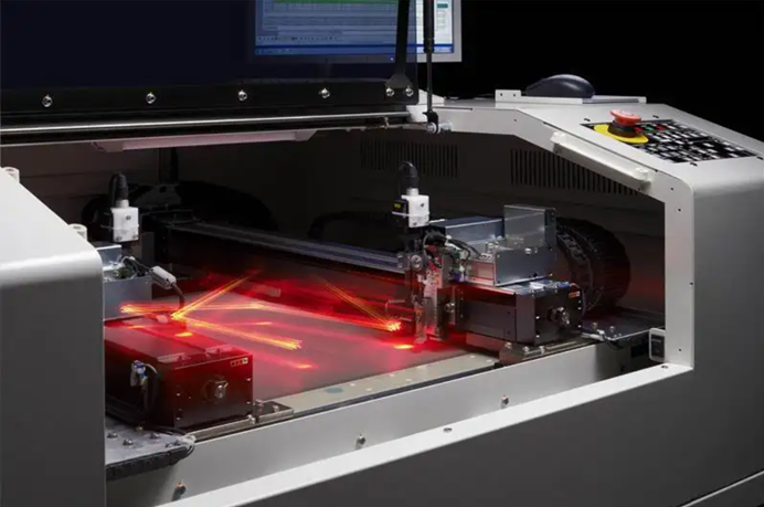
Flying probe testing replaces the needle bed with a probe and utilizes multiple motor-driven, fast-moving electrical probes to make contact with the pins of the device and perform electrical measurements. The introduction of flying probe testing has revolutionized the testing process for low-volume and fast-change assembly products.
Tests that previously required weeks to develop can now be completed within hours, significantly reducing product design cycles and time-to-market.
Fixture Test For Flexible PCB
The test accuracy and precision of the test fixture test are higher than that of the flying probe test because it allows for testing multiple FPC flexible circuit boards simultaneously. As a result, it is faster than the flying probe test. However, different types of FPCs require corresponding test fixtures. The price of a set of test fixtures varies depending on the number of test pads, thimbles, and the size of the FPC panel, ranging from hundreds to thousands of dollars. Test fixtures are recyclable.
Therefore, in mass production, manufacturers typically require customers to develop test fixtures. This approach helps save labor, reduces batch costs, improves test accuracy, and speeds up the overall production cycle.
For FPC testing, the shrapnel micro-needle module can be used as the connection module to enhance test efficiency. The shrapnel micro-needle module features an integrated shrapnel-type design, making it highly adaptable for small pitches. It can accommodate pitch values between 0.15mm and 0.4mm, offering stable and reliable performance.
The shrapnel micro-needle module can maintain long-term connection and current transmission. It can pass a large current of up to 50A, ensuring stable overcurrent, constant voltage, and no current attenuation within the same material body. It serves as an excellent connecting component.
The module has a service life of over 20 million cycles on average, making it a long-lasting component. It does not require frequent replacement during usage and exhibits highly stable performance.
FPC testing not only demonstrates high adaptability but also achieves high test efficiency.
AOI Test For Flexible Pcb
As a manufacturer of FPC flexible board cables, AOI testing plays an essential role in the production process of FPC flexible cables, especially for multi-layer FPC flexible boards or circuit structures with multiple layers.
AOI stands for Automated Optical Inspection, which is a process that utilizes optical principles to detect common defects encountered in welding production.
AOI is a rapidly developing test technology, and many manufacturers have implemented AOI test equipment.
During the automatic detection process, the machine scans the PCB using a camera, captures images, and compares the tested solder joints with the qualified parameters stored in the database.
After image processing, the defects on the PCB are identified, and they are displayed or marked for repair by maintenance personnel.

After the etching process, it is necessary to perform AOI optical scanning of each layer. Detect possible defects in each layer of the FPC flexible board cable.
So how does the AOI implementation process work? What are the points?
The steps of AOI optical inspection on the circuit layer of the FPC flexible board are as follows:
- Determine the number of layers of the FPC flexible board:
- Click to access the selection screen for item number and layer number.
- Check the product specifications based on the process card and production order sheet.
- Select the testing level and confirm the number of product layers.
- Use the drop-down box to select the required number of layers.
- A layer alignment for FPC flexible board line scan:
- Fix the FPC soft board to be tested on the pipe position nail (strip) correctly according to the displayed figure.
- Use the arrow keys to move the laser point, ensuring that the lower right tube pin is centered on the monitor.
- Align the laser point with the white crosshair on the reference image icon to ensure a precise match between the scanned image of the FPC flexible board line and the reference image.
- Scan and detect the A layer of the FPC flexible board cable:
- Enter the scan screen and set the scan parameters, ensuring all parameters are correctly set.
- Click the blue arrow button using the mouse to start the detection. After scanning, the carrier table will automatically return to its original position.
- Click the button to perform true and false point detection.
- Mark the places with problems and defects in the A layer:
- If any bad symptoms such as nicks, open circuits, or short circuits are detected during the AOI scan of the test layer, use a marker pen to mark the current layer.
- Perform damage calibration on the places marked on the A layer of the FPC soft board:
- For the layer with marked defects, use a blade to scratch the conductor for damage calibration.
- Repeat the above steps for testing other layers.
Secondly, the main points of AOI optical inspection for the circuit layer of the FPC flexible board. Why Use a Blade for Destruction Calibration?
- If the AOI identifies defective products and marks them as scrap for destruction, the marks will be visible in subsequent processes. The AOI will mark the defective products on the layer immediately after the AOI process.
However, for FPC multi-layer flexible board lines with solid copper surfaces on both sides, the marks may not be visible. In such cases where the outer layer has a solid copper surface, the conductor will be directly scratched with a knife (excluding the solid copper surface, the conductor can also be scratched with a knife) to create destruction marks. These marks will create bumps on the scratches, indicating that it is a defective product that cannot pass the electrical test. The subsequent processes will be able to see these marks.
- How to handle defective products identified in the electrical test after marking them as scrap?After identifying a defective product in the electrical test and marking it as scrap, the electrical test will proceed. Whether it is exposure, AOI, or electrical testing, multiple units are tested together.
Although a bad AOI mark may be visible before the electrical test, the immediate removal of the faulty unit does not occur. Instead, the entire page is tested. The display on the front display of the electrical testing machine will show the presence of defects (as the defects have already been marked with a knife). The corresponding mold cavity in the electric testing test frame will be identified to mark the faulty unit again. The final marking will be done during the full inspection of the OQC appearance.
The basic standards of flexible pcb testing can be divided into the following points
- Appearance of the FPC substrate film: Inspect the substrate for creases, wrinkles, bumps, and foreign matter attached to ensure optimal performance of the FPC.
- Appearance of the FPC cover layer: The surface of the cover layer should be free from defects such as bumps, folds, creases, and delaminations. Presence of any of these defects constitutes a defective product.
- Deviation between FPC connection pad and cover layer: The standard deviation should be within ±0.3mm for external dimensions below 100mm, and within ±0.3% of the external dimension for dimensions above 100mm.
- Leakage of FPC coating layer: The coating layer should undergo testing as per FPC solderability requirements. The conductor should not have tin attached to any leaked areas of the coating layer.
- Discoloration beneath the conductor of the FPC cover layer: After passing the humidity resistance test at 40°C and 90% humidity for 96 hours, the FPC should still meet performance requirements in terms of voltage resistance, soldering resistance, bending resistance, and bending resistance.
- Infiltration of FPC adhesive and cover layer: The degree of infiltration should be less than 0.2mm. At the connection plate, the deviation between the FPC cover layer and punching should meet the standard of a minimum ring width of g≥0.05mm.
- FPC electroplating combination: The FPC electroplating layer should not delaminate, and poor coating combination should not compromise the reliability of the FPC contact area.
Testing is the most effective method for controlling the yield of flexible PCB products. The shrapnel microneedle module serves as the ideal tool for FPC testing. Understanding the fundamental standards of FPC testing is essential for ensuring testing stability and improving efficiency, thereby achieving optimal performance. For detailed process capability standards of our company, please refer to this page.